USB Interface 10 Channel 12 Bit AD Data Acquisition STM32 UART ADC Module
Categories :
Wireless ModulesSKU :
1941961Product description:
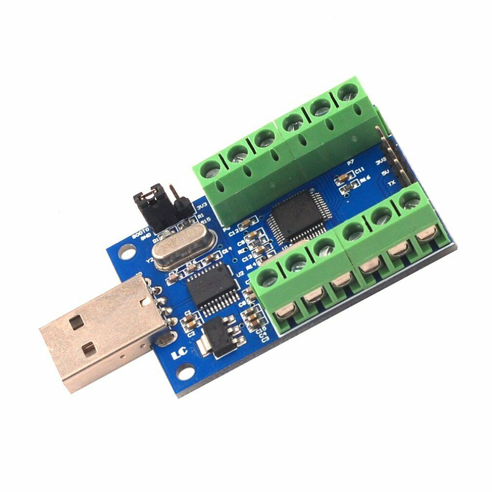
STM32F103 ADC module USES a series of single chip microcomputer STM32 10 road of the internal ADC 10 road resources as core sampling, takes to the sampling data by STM32 internal DMA transfer to memory, reduce the financial burden of the CPU and enhance the stability and accuracy of the AD sampling, at the same time onboard turn USB serial data transmission can be first place machine chip.
Features:
The onboard STM32F103C8T6 master control chip;
Onboard CH340 a serial port turn USB chip, convenient through the USB port on the PC to check the AD sampling results;
Reserve a UART serial communication interface, can answer the MCU;
Analog input channels: 10 channel single-ended input;
Sampling the voltage input range: 0-3.3 V.
Power supply voltage: 5 V / 3.3 V
Resolution: 12 Bit (4096);
The board size: 50 * 33 mm
The interface description:
IN0 - IN9: AD sampling voltage input;
GND: negative/sampling voltage interface;
The TX and RX: UART communication interface
Reserve 3 v3/5 V: 3.3 V / 5 V power supply input port
STM32F103 ADC module USES a series of single chip microcomputer STM32 10 road of the internal ADC 10 road resources as core sampling, takes to the sampling data by STM32 internal DMA transfer to memory, reduce the financial burden of the CPU and enhance the stability and accuracy of the AD sampling, at the same time onboard turn USB serial data transmission can be first place machine chip.
Function characteristics:
The onboard STM32F103C8T6 master control chip;
Onboard CH340 a serial port turn USB chip, convenient through the USB port on the PC to check the AD sampling results;
Reserve a UART serial communication interface, can answer the MCU;
Analog input channels: 10 channel single-ended input;
Sampling the voltage input range: 0-3.3 V.
Power supply voltage: 5 V / 3.3 V
Resolution: 12 Bit (4096);
The board size: 50 * 33 mm
1, the interface description:
IN0 - IN9: AD sampling voltage input;
GND: negative/sampling voltage interface;
The TX and RX: UART communication interface
Reserve 3 v3/5 V: 3.3 V / 5 V power supply input port
2, directions for use
(1) used on the PC
Turn USB serial interface chip CH340 driver installation, insert module to a computer, IN0 - IN9 after sampling the voltage anode, GND after sampling the voltage negative (that is, the total processing), open the serial debugging assistants, select the correct COM port and baud rate (115200), can see the AD sampling results, the sampling results 500 ms refresh time, customers can be modified on the basis of the source code for this time. Below is to connect IN0 - IN4 0 V, IN5 - IN9 3.3 V wiring diagram and the sampling results, from the test results although not specifically AD sampling chip, just use STM32 internal AD resources, but the precision is good.
(2) connecting MCU is used
If you want to use external MCU directly to obtain the sampling data, the MCU can be 3.3 V, RX and TX, GND module of 3.3 V, TX and RX, GND, of course, use 5 V to also can module power supply, about the serial data transfer protocol to view the source code.
(3) about the firmware update
If the customer wants to modify the source code, to write programs. Method is as follows: the module into the computer USB port, the jumper cap on the module into the 3 v3 end (note that after the completion of the burning to insert back to GND), open burning software FlyMcu, open the hex file, set the port number and baud rate and related parameters, such as "programming", then with forceps between the capacitance C9 (reset) on both ends.
Note:
The sampling voltage input IN0 - can receive all IN9 also can only meet part of when a certain way without sampling voltage input which the output result is a random value, unused port can also modify the program itself as an ordinary I/O port is used;
USES the voltage cannot be more than 3.3 V, or has the potential to damage the chip.

